Senior Design-2023
Valencia College
PROGRESS LOG
Week 1 - 01/10/2024-01/16/2024:
Group:
In the initial week, we conducted tests on the Power module by employing the PoE protocol to supply power to the Raspberry Pi. The configuration is depicted in the image below.
Simultaneously, we executed a preliminary test on the Network module by disabling the WiFi on the Raspberry Pi and executing the program via Ethernet.
However, modifications were necessary in the code as the pump logic and the User Interface were initially running on the Raspberry Pi. To facilitate running the code from a host PC over LAN, a new library had to be implemented. This approach differed from the previous method, which involved using the Raspberry Pi to run the program.
Furthermore, we conducted research on configuring the network settings on the Raspberry Pi to enable communication via Ethernet, transitioning from our previous reliance on WiFi [12].
Week 2 - 01/17/2024-01/23/2024:
Group:
This week we got together to begin the construction of the capsule. Our primary focus was to ensure the precision of measurements before proceeding with the cutting of the metal sheets. To achieve this, we created a cutting template, as depicted in the image below.
In the visual representation, the inner circle marks the interior of the cylinder, while the outer circle corresponds to the outer perimeter of the metal plate. The space between these circles is the only space available for the installation of copper piping and threaded rods, this is why careful planning is necessary before proceeding to cut the metal plates.
The image below provides a bottom view of the lower plate, illustrating the intended hardware configuration that ensures uniform pressure distribution around the cylinder. It also shows how the copper piping loops will be positioned beneath the capsule.
Moving on to the next image, it shows the upper plate and the selected hardware – wing nuts – chosen for their convenience in facilitating easy access to the interior of the capsule.
The final image portrays the acrylic cylinder and the threaded rods. With comprehensive planning completed, we are ready to begin the drilling and soldering phases next week.
Week 3 - 01/24/2024-01/30/2024:
Alex:
Before commencing the construction of the copper pipe radiator, it was necessary to calculate the minimum length of copper piping required for the effective dissipation of heat generated by the CPUs in our cooling system. This estimation is crucial in ensuring an adequate surface area for effective cooling of the computers' CPUs.
To estimate the required surface area for our system the following equation was used [13]:
Q = U⋅A⋅ΔT
Where:
1. (Q) Heat Load: This is the amount of heat generated by the components measured in (W).
2. (ΔT) Temperature Difference: This is the temperature difference between the coolant entering and leaving the system(°F).
3. (U) Heat Transfer Coefficient: This is a measure of how well heat is transferred between the components and the coolant.(Btu/ft² h°F )
4. (A) Surface Area: is the surface area of the radiator(ft²)
Measuring Heat Load (Q)
To determine the Heat Load, a test was conducted by running a new stress test on the Raspberry Pie while at the same time measuring its power consumption using a Power meter. The frequency used was 1800MHz as done in previous tests. As can be seen in the image below, the Raspberry Pi's consume around 6W of power per unit during peak stress conditions, giving us a total Q = 12W or 40.9 Btu/hr.
Measuring the temp. difference (ΔT)
The temperature difference entering and leaving the cooling block was measured during the test above. A temperature probe was placed both at the entrance of the cooling block and its exit, measuring a temperature difference of ΔT = 3°F
Finding out the Heat Transfer Coefficient
The last quantity was to find out the Heat Transfer Coefficient between the copper pipes and the coolant( distilled water). From a table found on engineersedge.com [14], the Heat Transfer Coefficient was found to be around 50 ft² h°F.
Calculating the total length of Copper
Rearranging Q = U⋅A⋅ΔT we have A = Q/ U⋅ΔT
A = 40.9 /50⋅3 = 0.2726ft²
Taking this result in square feet and using the equation for the surface area of a pipe, the length of the pipe can be calculated as follows:
1/2inch to ft = 0.04166667ft
A = 2π⋅(d/2)⋅l or lenght = A/(2π⋅(d/2))
Length = 0.2726/2π⋅(0.04166667/2) = 2.1 ft
Conclusion: In conclusion, despite our system featuring more than the calculated 2.1 feet of half-inch copper pipe, the calculations assure us that we have sufficient piping to meet our heat dissipation needs.
Group:
Phase 1: Watertight Test
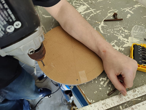
During this week, our primary goal was to guarantee the watertight integrity of the capsule. To accomplish this, our initial step involved marking the plates to align the holes on the bottom plate with those on the top plate, as illustrated in the image below. Following that we affixed the previously created template and drilled through both plates.
Upon completing the drilling process, our next task was to apply a thin layer of foam padding, intended to function as a temporary rubber gasket, ensuring the capsule's watertight seal. However, this foam will soon be replaced with an actual rubber gasket, which we anticipate will provide superior results.
With the capsule fully assembled, we proceeded to conduct underwater testing. The testing phase involved submerging the capsule for a duration of 15 minutes, while visually inspecting for any air bubbles. This first test yielded excellent results, as there was no water present inside the capsule after verification nor bubbles were seen emerging during the test.
Phase 2: Air Pressure Test
In this phase, our objective was to put the capsule through an air pressure test, aiming to establish an efficient means of detecting the presence of water. By pressurizing the capsule, we not only can detect a water intrusion faster but also gain valuable time, as air must escape the capsule before water can enter.
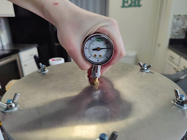
Once we were confident that the capsule could effectively prevent water entry, the subsequent step involved tapping a hole in the top plate and installing an air pressure valve, as depicted in the picture below. This valve would be necessary to introduce the necessary air pressure to the capsule.
After securing the fitting in place, we pressurized the capsule to 10 PSI and conducted an underwater test. Unfortunately, this initial test failed, evident from water bubbles emerging from both the top and bottom plates. We then ran the test once more, this time tightening the threaded rods further and reducing the pressure to 5 PSI. The second attempt proved successful, with no signs of water infiltration.
Phase 3: Copper Radiator Construction
Moving on to the construction of the copper radiator, our first step was to cut the copper pipes to an appropriate length. We opted for 9-inch-tall pipes that would extend nearly to the top plate.
To secure the radiator structure and utilize the bottom plate as a support, we proceeded to drill holes slightly larger than the diameter of the 1/2-inch pipes. The illustration below provides a visual of how the copper pipes will be arranged into the capsule.
Upcoming Work:
In the upcoming week, our primary objective is to complete the construction of the copper pipes and finalize the soldering work. We also plan to drill a hole into the top plate to accommodate the entry of an Ethernet cable into the capsule where data and power will be introduced.
Following the drilling process, we will seal the hole and conduct another pressure test to ensure the capsule's ability to maintain the desired pressure levels even after modifications. From this point, we can begin to add the electronics into the capsule.
Leonardo:
Updated Engineering Specifications table with pressure sensor data; added Weekly Meetings and Time and Effort.
Week 4 - 01/31/2024-02/06/2024:
Group:
This week, we resumed where we had left off, having completed the drilling for just one loop of copper. Our first step was to drill the remaining holes in the bottom plate. With meticulous measurement and drilling, we achieved the final result depicted in the image below.
Once the holes were finished, we moved on to soldering the copper loops, utilizing the plate to establish the length of the horizontal pipes. This ensured that each loop would fit perfectly, compensating for any potential imperfections in hole placement. The image below illustrates how the loops were soldered.
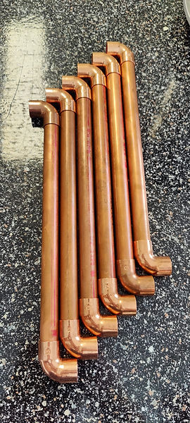
We then proceeded to stage the copper loops before soldering them with the bottom horizontal pipes as seen in the below picture.
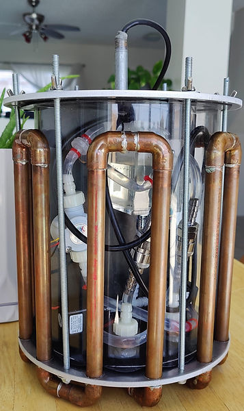
After positioning the threaded rods, we proceeded to solder the horizontal pipes. At this stage, the only remaining task to complete the radiator was to drill new holes for the inlet and outlet, as depicted in the image below.
With the radiator fully constructed, we moved on to drilling a center hole in the top plate to facilitate the power and communication cable entering the capsule. To ensure air would not escape the capsule through the newly drilled hole, we used a 2-inch pipe filled with Butyl tape.
Butyl tape is a synthetic rubber adhesive that has the property of being compressed into tight spaces and later expands as it is left to rest. It also does not harden which allows it to remain flexible. This was crucial for our design as it allowed the capsule to remain airtight even when the cable was moved around. The image below shows the finalized physical construction of the capsule.
Test and Results:
After completing the above-mentioned steps, we pressurized the capsule to 10 psi. This time, we replaced the foam gaskets with rubber ones for improved sealing. Furthermore, we installed the power and communication cable, along with the entire copper radiator to the capsule. To conduct a thorough test for air leaks, we pressurized the capsule and submerged it underwater. This allowed us to identify the location of any air leaks in both the capsule and the copper pipes.
The results were largely positive, with no leaks detected in either the copper pipes or the cable entrance. However, we did identify a leak through the inlet and outlet pipes. This was attributed to the solder not adhering properly to the aluminum plate during the soldering process for these pipes.
To rectify this issue, we carefully filled the gap between the copper tubes and the aluminum plate with butyl tape before conducting another test.
Ultimately, the test yielded positive results, with no air leaks observed underwater. Additionally, we maintained the capsule pressurized for a full 24-hour period to monitor the stability of the air pressure, which remained consistent throughout as seen in the images below.
before after
Upcoming Work:
In the upcoming week, our main focus will be on arranging the components within the capsule and mounting them onto a backplane. Alongside this task, we'll weigh all components and calculate the required added weight to offset the buoyancy of the capsule. Finally, we'll assemble the water pump system and conduct testing to test its functionality.
Week 5 - 02/07/2024-02/13/2024:
Alex:
This week, I dedicated my efforts to tying up some loose ends before proceeding with mounting the capsule's inner components. My first task involved testing the water pumps to assess their capacity to individually move water along the copper pipe loops. This will also retest the copper pipes for any water leaks. The test involved running a single pump individually to gauge its effectiveness in propelling water through the system. The setup included a single pump, the designated water reservoir, and several pieces of rubber tubing, as demonstrated in the video provided below.
Results:
The results were positive; a single pump has the capability to effectively circulate water throughout the entire copper pipe system, and no leaks were found. Furthermore, to ensure a clear understanding of how the complete water system would be interconnected prior to physical construction, I prepared a schematic diagram which is illustrated in the image below.
This configuration allows each pump to run individually or together, depending on the user's preference. Additionally, the check valves ensure that when only one pump is running, water is not drawn from the secondary branch, preventing a false reading that the secondary pump is operational. This visual reference will serve as a guide when constructing the water system components during the assembly phase.
Mounting the Raspberry Pi's
Furthermore, I focused on mounting the Raspberry Pi's, the cooling blocks, and the PoE hats to a board that will act as a mounting plate.
Before doing this I needed to address the challenge of both the PoE adaptor and the water cooling blocks needing to occupy the same space above the Raspberry Pi. Initially, we planned to use ribbon cables to connect the GPIO pins from the Raspberry Pi to the PoE adapter, aiming to position the PoE adapters away from directly above the Raspberry Pi, where the cooling block needed to be installed. However, the ribbon cables proved to be too large for our application and interfered with the mounting screws.
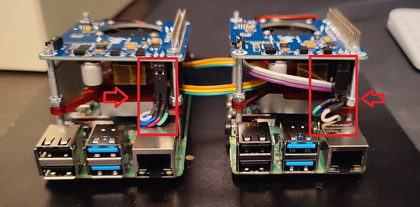
To tackle this issue, I decided to create a small connector made up of just the necessary cables to allow the Raspberry Pi to be tethered to the PoE hats, pictures below.
This adjustment enables the cooling blocks to sit directly over the CPU, while also allowing the PoE hats to be mounted to the same mounting screws holding the Raspberry Pi's, as we had initially intended.
Adding the pressure sensor to the control module
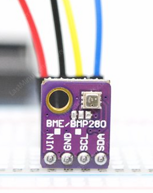
Lastly, I had a chance to incorporate the pressure sensor into the control module. The pressure sensor we decided to go with was the BME-280. This sensor consumes very low power and has the ability to measure not only air pressure but also air humidity and temperature. Considering these added capabilities, it was decided to replace the DHT-11 for the BME280.
DHT-11 BME-280
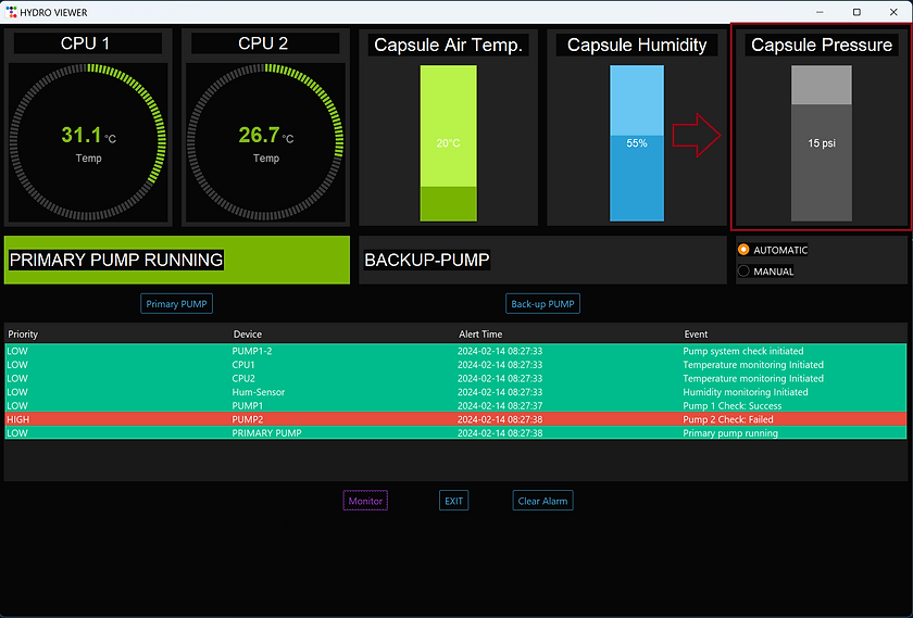
The BME-280 Measures atmospheric pressure in relation to sea-level known as relative pressure. For this reason when the sensor is not in a pressurized environment the pressure reading is equal to 1022hPa(hectopascals) or 14.8 psi. This reading was then converted to psi and zeroed out in the script to display the correct pressure difference. Finally, a new gauge was added to the User interface to display the newly added sensor reading.
Week 6 - 02/14/2024-02/20/2024:
Group:
This week, we gathered to collaborate on assembling the components within the capsule. We utilized two distinct boards: one for mounting electromechanical components and another for housing the majority of the electronics. To facilitate coolant circulation across the panel, we drilled two holes, enabling movement from the reservoir to the cooling blocks positioned on the opposite side. Additionally, another aperture was created to reintroduce the coolant into the remaining cooling system. Most of the components were staged using double-sided tape, which will later be replaced with a more permanent method.
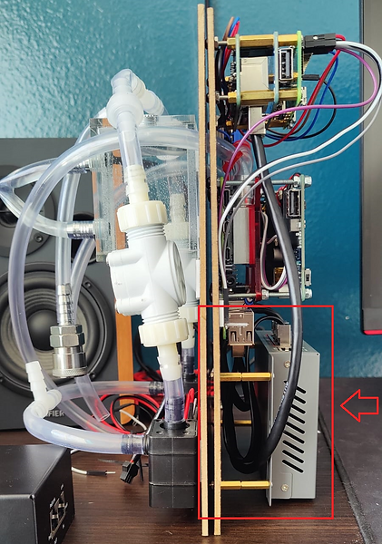
Next, we proceeded to assemble the other side, which houses the remaining components. As depicted in the photo below, the available space is limited. As a result, we had to position the switch away from the panel to ensure adequate room for the Ethernet cable connectors to fit. This adjustment not only permitted proper fitting of the connectors but also provided us with the space needed to organize the additional Ethernet cables seen in the image below.
Even with these efforts, we still encountered issues with available space in the capsule. Due to the size of the reservoir fittings, the electromechanical side pushes the electronics too close to the walls of the acrylic cylinder, as seen in the image below.
To address this issue, we will be replacing the straight fitting with a right-angle fitting. This adjustment will reduce the amount of space required for directing the tubing downwards. Additionally, we will relocate the controller module closer to the center of the mounting board. A front view of the electronics board is shown below.
Our final efforts for this week focused on integrating quick disconnects into the water loop. This addition will enable us to easily disconnect the electronics board from the radiator of the capsule without the risk of water spillage, as the quick disconnects prevent leakage.
Week 7 - 02/21/2024-02/27/2024:
Group:
Wire Managing the capsules components
We met this week on three different occasions, the first meeting involved wire managing all of the cables inside the capsule, this involved carefully planning how the cables would be routed inside the capsule as well as connecting the flow and barometric sensors to the controller (PiZero). The PoE hats were also connected to the relays to supply power to the pumps situated on the opposite side of the capsule. To keep things organized and prevent wire clutter we drilled holes through the mounting board and hid most of the excess wiring between the two mounting plates holding the electronics and the water circuit on the other side. The results of our efforts are depicted in the following two images.
Configuring the LAN network
During the second meeting, our focus shifted to configuring the Raspberry Pi units to operate over a LAN. This adjustment was necessary as relying on WiFi connectivity would be impossible when the capsule is submerged underwater. However, while attempting to establish a LAN between the client computer and the Raspberry Pis, we encountered a roadblock. One of the computers refused to use the IPv4 protocol. After plenty of troubleshooting, it was discovered that the issue lay with the patch cable being too short. We presume we had an issue with reflection and distortion as the cable was too short. More on this on the following website [14]. The cable was replaced and the network was tested.
Testing Capsule underwater
With all the components in the capsule and all the cabling managed, we moved on to testing the capsule underwater. This test had been conducted successfully in the past, although without any components present. Unfortunately, the capsule's pressure would not remain stable due to an air leak originating from the Ethernet cable itself. While the entire capsule did not exhibit any air leaks, it was discovered that the Ethernet cable was indeed leaking air. This can be seen in the short clip below.
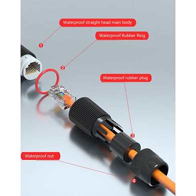
To address this issue, we will need to ensure the Ethernet cable is airtight. Our solution involves using a waterproof coupler, images below, that will be added inside the capsule. This approach not only prevents air from escaping but also simplifies cable management within the capsule, eliminating the need to accommodate three extra feet of cable.
Test Trials for Engineering Requirements
LOW-LEVEL Requirement: The product shall operate at a very low noise level:
To evaluate the requirement of operating at a very low noise level, we began by measuring the ambient noise level to establish a baseline, which resulted in around 50 dB. Following this, we operated the equipment and measured the noise level produced. The results showed that while our system was running, the noise level increased by only 7 dB meeting our requirement to stay below 35 dB.
2nd MID-LEVEL Requirement: The product shall Incorporate redundancy measures to ensure continued operation in case of component failures:
In the following video, we demonstrate the system's capability to remain operational even after one of the pumps has failed or stopped operating. Furthermore, in the event of a secondary pump failure, the system will make one final attempt to start the primary pump before notifying the user that the system is non-operational. We will simulate each pump failure by removing power from the pumps.
3rd HIGH-LEVEL Requirement: The product shall allow the computers inside the capsule to communicate with the client PC:
To fulfill this requirement, we relied on establishing a Local Area Network over Ethernet, as WiFi communication is not viable underwater. To test and validate connectivity, the following video demonstrates the use of VNC and a tool called Advanced IP Scanner to showcase the network connection between the computers. It's crucial to note that WiFi capabilities are disabled in all four devices during testing.
Future Work:
-
Finish validating the last three Engineering requirements.
-
3D print brackets for water reservoir, pumps, and hall sensors.
-
Install LED lights on the capsule and test with the User interface.
Week 8 - 02/28/2024-03/05/2024:
Group:
This week, our primary objective was to validate the last three engineering requirements. Our efforts commenced with the addition of a few more lines of code to ensure that the user receives a notification whenever the capsule experiences a one psi drop in air pressure. This was achieved through two means: Firstly, the user will observe a timestamp along with an error message displayed in the event log. Additionally, an alarm will be triggered on the host computer each time this event occurs. Furthermore, we incorporated a louder alarm feature, activated when the capsule's psi drops below 5 psi. These features will be shown under the 1st MID-LEVEL Engineering Requirement below.
1st MID-LEVEL Requirement: The product shall grant the user the ability to remotely monitor and control capsule pump operation, monitor air temperature, read humidity levels...
The following video will demonstrate the air pressure monitoring and failure system in the event of pressure loss.
In the following video, the humidity and air-pressure monitoring will be validated by administering hot air to the capsule.
Finally, pump selection using the user interface is demonstrated.
1st HIGH-LEVEL Requirement: The product shall maintain the temperature of computers 10-20°F lower than conventional Air-cooling solutions.
We began this test by pressurizing the capsule and submerging it underwater. We conducted the same test as previously performed during our mock tests, utilizing identical values for time and frequency to overclock the computers.
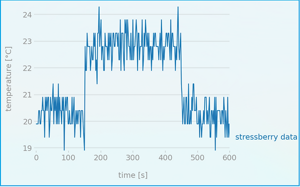
CPU1 Stress test results
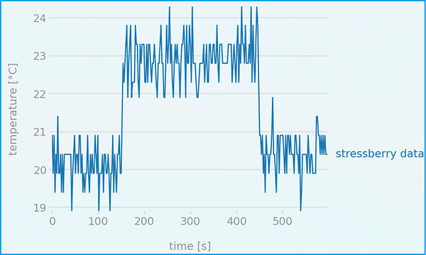
CPU2 Stress test results
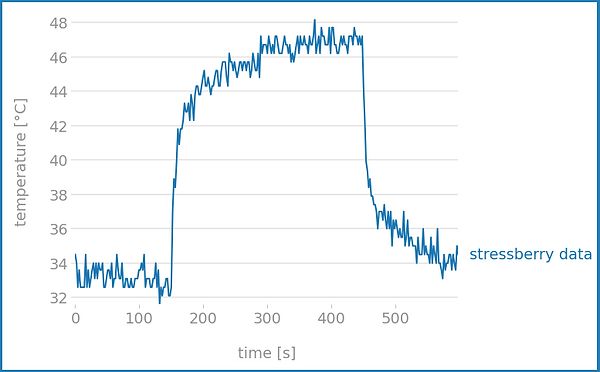
Conventional Air cooling Stress test results
Comparing these results with those previously obtained using conventional air cooling methods, we achieved a peak temperature reduction of 23.8°C or 42.8°F. The table provided below presents the list of tests along with their respective results.
2nd HIGH-LEVEL Requirement: The product shall ensure that water is effectively kept out of the capsule housing the electrical components.
We initiated the validation of this engineering requirement by pressurizing the capsule to 10 psi and submerging it underwater. The plan was to monitor the pressure continuously and record footage for 24 hours. However, we encountered an issue as the camera we were using failed to record any footage. Therefore, we will need to attempt this process again.
Fabricating Brackets for Reservoir and Pumps
Lastly, we visited the 3D printing lab, where we received assistance in fabricating the brackets required to securely hold the reservoir and pumps in place. Below are the images of the 3D brackets that were sketched.
Week 9 - 03/06/2024-03/12/2024:
Group:
This week, we met once more to continue our efforts in installing the brackets for the reservoir and water pumps. While making adjustments to the capsule, we also decided to swap out the plastic tubing for a more rigid option. The previous tubing tended to compress under pressure, restricting the flow of water within the capsule. The newly installed tubing is made out of thicker walls, enabling it to bend without creating kinks and maintaining its shape even under 10 psi of pressure.
Engineering Requirements
2nd HIGH-LEVEL Requirement: The product shall ensure that water is effectively kept out of the capsule housing the electrical components.
After resolving the issues we had with the camera, we finally had a chance to record the last outstanding engineering requirement. The footage was recorded over 24 hours, keeping the capsule submerged underwater while simultaneously monitoring the humidity and air pressure. The results were positive, with no increase in humidity and no air pressure lost. See Video Clip Below.
The remainder of the week was dedicated to finishing chapters one and two of the report, with each of us completing one chapter.
Week 10 - 03/20/2024-03/26/2024:
Group:
This weeks focus was mainly on completing the reminding sections of the report. A few other items were taken care of which are the following:
-
We Updated the Power Budget as we decided to go for a more power efficient led strip. The power consumption was measured and the Power budget was updated.
-
We also worked on creating the circuitry to drive the LED to make sure the LEDs are compatible with the Raspberry Pi. Pictures below.
Week 11 - 03/27/2024-04/02/2024:
Alex:
After constructing the circuit depicted above, the LEDs were mounted within the capsule. One portion of the LED strip was affixed to the top section of the cylinder to enable data and power transmission from the Raspberry Pi Zero. Simultaneously, another strip was affixed to the bottom section of the capsule. Both strips were interconnected in series to ensure synchronous operation.
The LEDs are intended to provide users with visual cues regarding any failures occurring within the capsule. Additionally, users have the option to customize the ambient color according to their preferences. It is important to note that in the event of a failure, the indication should overwrite the user-defined ambient color. The video below demonstrates this operation.
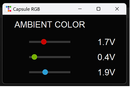
To prevent the UI from becoming overly cluttered, I implemented a separate window that appears upon pressing the color button. This additional window enables users to individually adjust the voltage level of each LED, thereby allowing them to create their desired color scheme.
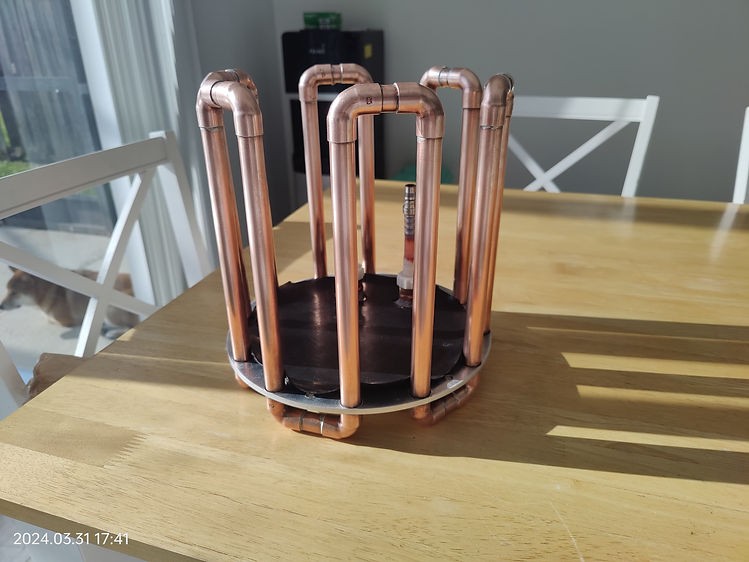
Lastly, the copper pipes underwent brushing to eliminate any dirt and residue accumulated during the construction of the capsule.